
What Site Survey Data Is Needed for a Ground-Mounted Solar Project?
Planning a big ground-mounted solar installation but feeling lost in a sea of technical requirements? You're not alone. Many project developers and EPCs send out requests for quotes with incomplete information, which unfortunately leads to vague pricing, unexpected design changes, and costly project delays. The key to avoiding this is understanding what site survey data is needed for a ground-mounted solar project before you even start talking to suppliers.
The necessary site survey data for a ground-mounted solar project isn't a single, universal checklist. Instead, it's a specific set of information covering geotechnical conditions, site topography, and local environmental loads (wind and snow). This data allows engineers to design a safe, cost-effective, and durable mounting structure and foundation tailored to your exact location.
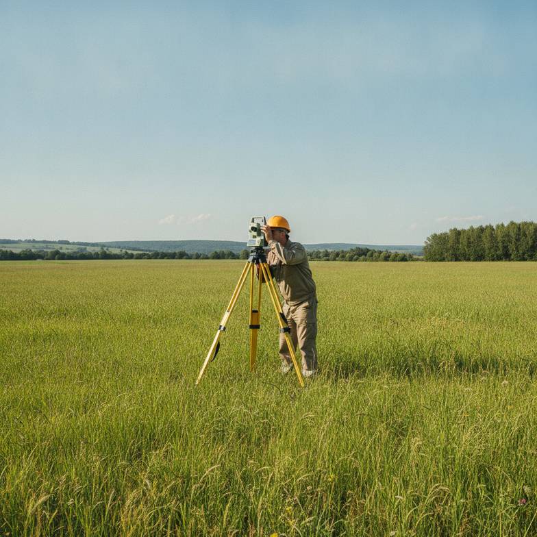
Getting this data right is the difference between a rough budget guess and a firm, engineered proposal you can actually build on. So, let's dive into the specific data points we, as a mounting supplier, need to see and, more importantly, why each one is so critical for your project's success.
What Geotechnical Data Is Crucial for Foundation Design?
Are you worried about choosing a foundation that won't hold up over time? Picking the wrong foundation type—or under-designing it—is one of the most expensive and dangerous mistakes you can make in a ground-mount project.
A professional geotechnical report is the solution. It provides essential values like soil bearing capacity, corrosivity, and frost depth. This information is non-negotiable for selecting the right foundation—like ground screws versus concrete piers—and ensuring your investment remains stable for decades.
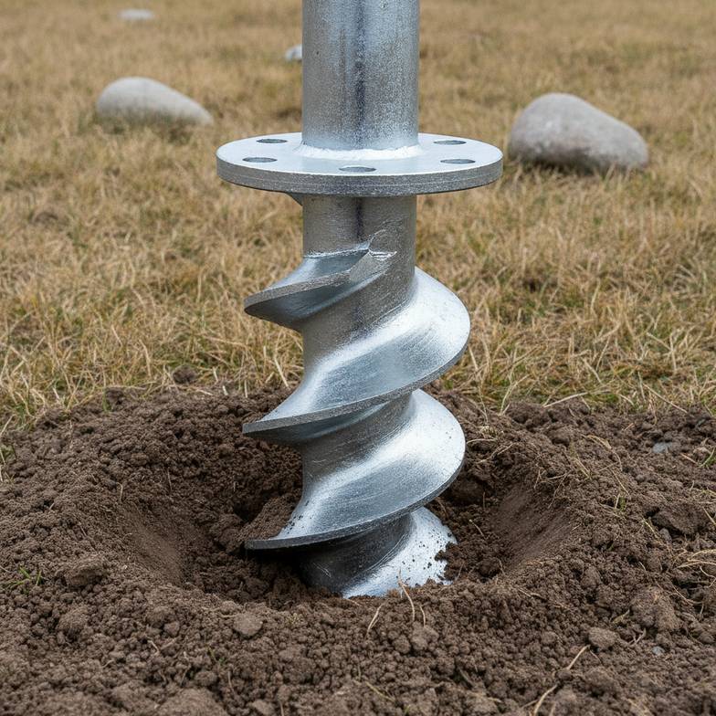
Dive Deeper: From Soil Samples to Structural Security
When we receive an inquiry for a ground-mounted system, the first document I often ask for is the geotechnical survey. It’s the foundation—literally—of a sound structural design. Without it, any engineering is just guesswork. Here’s what we're looking for inside that report.
Soil Bearing Capacity: Can the Ground Hold the Weight?
This tells us how much load the soil can support without shifting or failing. A low bearing capacity, common in loose sands or soft clays, means you need a foundation that distributes the load over a wider area or goes deeper to reach a more stable soil layer.
High Bearing Capacity: Dense, stable soils might allow for shorter, more cost-effective driven piles or ground screws.
Low Bearing Capacity: Softer soils might require larger concrete ballasts, helical piles with wider blades, or longer piles to achieve the necessary resistance.
Some reports also include results from on-site pull-out tests, which are fantastic. This test involves installing a sample pile and measuring the force required to pull it out. It provides real-world data that validates the engineer's calculations and gives everyone much higher confidence in the chosen foundation design.
Soil Corrosivity: Will Your Structure Rust from Below?
A steel foundation pile can look perfect on day one, but if the soil is highly corrosive, it could be dangerously weakened within a few years. The geotechnical report analyzes factors like soil resistivity, pH levels, and the presence of chlorides and sulfates to classify its corrosivity.
This data directly impacts the material specifications for the foundation and racking:
| Soil Condition | Potential Material Specification | Why It Matters |
|---|---|---|
| Low Corrosivity | Standard galvanized steel (e.g., G90) | A cost-effective solution for benign environments. |
| Moderate Corrosivity | Thicker galvanization (e.g., G235) | Provides a longer service life before corrosion begins. |
| High Corrosivity | Thicker coatings, specialized alloys, or even aluminum | Prevents premature structural failure and protects the project ROI. |
Ignoring soil corrosivity is a gamble I never recommend taking. The small upfront cost of a better coating is tiny compared to the cost of replacing a failed structure.
Frost Depth: Avoiding Heave and Instability
In colder climates, this is a huge deal. When water in the soil freezes, it expands, and this expansion can literally push foundations and posts right out of the ground—a phenomenon called "frost heave." The geotechnical report will specify the local frost line, which is the maximum depth at which the ground freezes in winter. To prevent heave, all foundations must be anchored below this line. This directly influences the required length of ground screws or the depth of concrete footings.
How Does Topography Affect Your Ground-Mounted Solar Project Layout?
Working with a sloped, rolling, or uneven piece of land? Simply ignoring the site's terrain can destroy your installation schedule, inflate your civil work budget, and lead to a poorly performing array.
A topographical survey, which maps out the site's elevations and contours, is essential. This data allows for an optimized array layout, minimizes the need for expensive grading, and helps ensure every module is properly aligned for maximum production and proper water drainage.
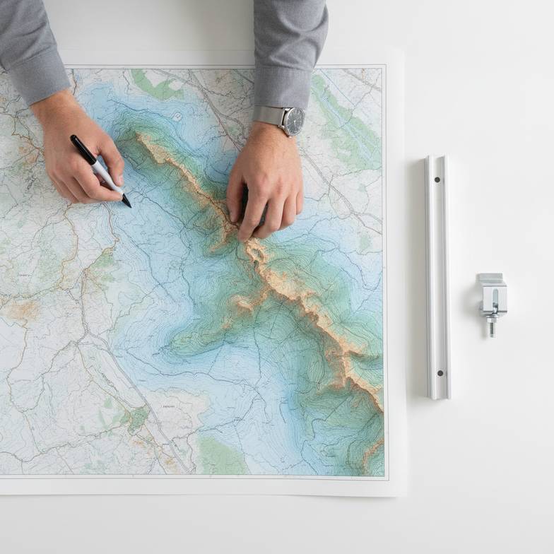
Dive Deeper: More Than Just a Flat Map
For a preliminary budget quote, a Google Earth screenshot might give us a general idea. But for a final, buildable design, we need a professional topographical survey. This survey moves beyond a 2D picture and gives us a 3D understanding of the site, which is critical for several reasons.
Slope and Gradient Analysis
A perfectly flat site is rare. Most have slopes and undulations. A topographical survey provides detailed contour lines that allow us to:
Optimize Layout: We can position rows of panels to follow the site's natural contours, which can dramatically reduce the need for expensive earthmoving and grading.
Manage Shading: On east-west slopes, the slope angle affects sunrise and sunset shading. On north-south slopes, it changes the optimal tilt angle and inter-row spacing needed to prevent panels from shading each other.
Assess Racking Suitability: Some ground-mount systems are designed to accommodate slopes of up to 15-20% with adjustable components. Other, more rigid systems require a nearly flat surface. The topo data tells us which product family is a viable option for your site.
I've seen projects where a failure to account for a 10% grade forced a last-minute switch to a more expensive racking system with greater adjustability, a surprise that could have been avoided with an early topographical survey.
Identifying Obstructions and Setbacks
The survey should map out everything that defines the usable project area. This includes:
Existing Structures: Buildings, sheds, and wells.
Natural Features: Large trees, wetlands, and rock outcroppings that can't be moved.
Utilities: Overhead power lines, underground pipes, and utility easements.
Property Boundaries: Legal setbacks from property lines that restrict where you can build.
By mapping these elements accurately, we can design a layout that maximizes the number of panels within the buildable area, avoiding costly rework or violations.
Planning for Access and Staging
Solar projects involve heavy equipment and tons of materials. The topographical map is a key logistics tool. It helps plan:
Access Roads: The best routes for delivery trucks to enter and navigate the site.
Staging Areas: Flat, stable areas where components like rails, posts, and panels can be safely stored and organized before installation.
Without this, you risk trucks getting stuck or having to stage materials far from the installation area, wasting time and labor.
Why Are Wind and Snow Loads the Most Important Site Survey Data for a Ground-Mounted Solar Project?
Do you ever worry that a single powerful storm could damage or even destroy your entire solar array? Underestimating local wind and snow forces is a direct path to catastrophic failure, turning a valuable asset into a pile of scrap.
The solution is to use precise, code-compliant environmental load data. The required site survey data for a ground-mounted solar project must include the design wind speed and ground snow load, as specified by a qualified engineer referencing local building codes like ASCE 7. This is the only way to engineer a structure that will reliably stand up to Mother Nature.
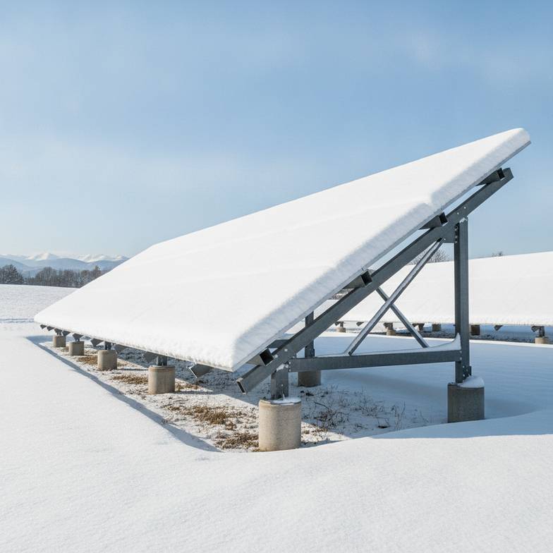
Dive Deeper: Engineering for the Elements
When we design a mounting system, we are essentially building a field of "sails" that have to resist powerful forces for 25+ years. The wind and snow load data tells our engineers exactly how strong those forces will be. It's not just about one number; it's about several factors that create a complete picture of the environmental risks.
Understanding Wind Load Calculations
A client telling us "we have 115 mph winds" is a start, but it's not enough information. A proper wind load analysis, typically done by a structural engineer, considers several factors from the ASCE 7 standard (or the relevant local code):
Basic Wind Speed (V): This is the starting point, based on maps that show wind speeds for different regions.
Risk Category: This classifies the building or structure based on its use. A solar farm powering a hospital (Category IV) requires a more robust design than one for a farm shed (Category I). Most commercial solar projects fall into Category II or III.
Exposure Category: This describes the surrounding terrain. A project in a wide-open, flat field with no obstructions (Exposure C) will experience much higher wind forces than one in a suburban area surrounded by buildings and trees (Exposure B).
Topography Factor (Kzt): If the project is on a hill or escarpment, the wind can speed up as it flows over the terrain. This factor accounts for that acceleration.
Failing to account for these variables can lead to a structure that is either dangerously under-engineered or needlessly over-engineered and expensive.
The Impact of Snow Load
For projects in northern latitudes, snow is a major structural concern. We need the Ground Snow Load (Pg), which is also determined from code-based maps. This isn't the same as the amount of snow you see in a single storm; it's a design value that accounts for decades of weather data.
Engineers use this to calculate the design snow load on the panels, considering:
Panel Tilt: Steeper tilts shed snow more easily but also catch more wind.
Drifting: Wind can cause snow to accumulate unevenly, creating drifts at the lower edge of an array or in between rows. This unbalanced load can be a major point of stress.
Sliding Snow: Snow sliding off one row of panels can pile up on the row below it, creating an immense load that must be accounted for in the frame and foundation design.
Here’s a simple breakdown of why we need this data:
| Data Point | Why We Need It | Design Impact |
|---|---|---|
| Basic Wind Speed (V) | To calculate the base wind pressure on the array. | Determines the required strength of rails, posts, and clamps. |
| Exposure Category | To adjust wind pressure based on surrounding terrain. | An open field (Exposure C) requires a stronger structure than a sheltered one. |
| Ground Snow Load (Pg) | To calculate the maximum weight of snow the structure must support. | Dictates the thickness of steel/aluminum profiles and foundation size. |
| Frost Depth | To ensure foundations are not pushed up by freezing soil. | Determines the minimum length of piles or depth of footings. |
Getting this data from a qualified professional is not just a best practice; it's essential for safety, insurability, and the long-term bankability of your project.
Frequently Asked Questions
Can I just use Google Earth for my site survey?
For a very early, preliminary budget estimate, Google Earth can be helpful for a general sense of the site layout and potential obstructions. However, it is not accurate enough for final engineering. You need a professional topographical survey to get precise elevations, slopes, and boundary lines needed for a safe and efficient design.
What if I don't have a geotechnical report?
For very small residential projects, a visual inspection and knowledge of local soil might sometimes be accepted, but it carries risk. For any commercial-scale project, a geotechnical report is essential. Without it, an engineer must make conservative assumptions, which often leads to an over-designed and more expensive foundation. Or worse, you risk foundation failure.
How much does a professional site survey cost?
Costs vary significantly based on the project size, location, and scope of work. A geotechnical investigation might cost a few thousand dollars, while a topographical survey could be in a similar range. While this may seem like an added expense, it's a small investment to de-risk a project worth hundreds of thousands or millions of dollars.
Does the solar module I choose affect the site data needed?
The module choice doesn't change the site data you need to collect (soil, wind, snow are independent of the panel). However, the module's specific dimensions, weight, and clamping zones are critical pieces of information that we combine with the site data to perform the final structural calculations. Always provide the module's official datasheet with your RFQ.
Conclusion
Ultimately, gathering the right site survey data for a ground-mounted solar project isn't about ticking boxes on a generic checklist. It's about conducting a thorough investigation to understand the unique risks and conditions of your specific site. From the soil's ability to support the structure to the wind and snow it must endure, this data is the foundation of a safe, reliable, and cost-effective design. It empowers a supplier like us to move beyond guesswork and provide you with a truly engineered solution that you can trust for the long haul.
Ready to turn your project requirements into an actionable proposal? Submit your site survey data, project drawings, and module specifications to our team. We'll help you configure the right ground-mounted solar solution and provide a clear, detailed quotation for your project.
Written by
XINVOK Technical Team
Practical solar mounting knowledge for EPC teams, distributors and project buyers.
Project inquiry
Talk to Our Team
Share your project location, module size, mounting type, quantity and customization requirements.
Related Products
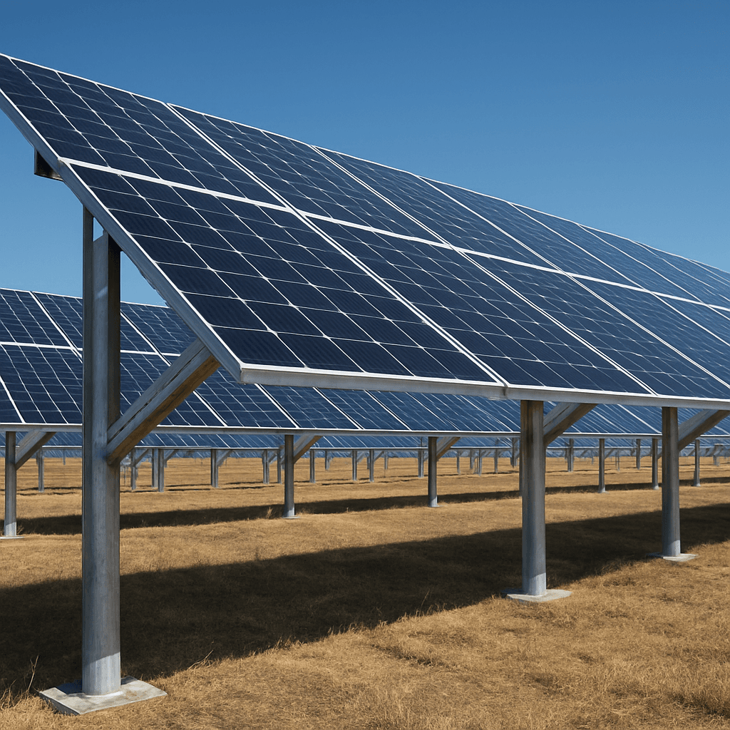
Ground Solar Mounting Systems
Aluminum, pile and galvanized steel ground mounting options for commercial and utility PV projects, selected according to soil condition, foundation method and project layout.
View products
Ground Screws
Galvanized ground screw foundation products for ground solar mounting systems, selected according to soil condition, diameter, length and pull-out requirements.
View products