Solar Mounting on Sloped Land: Layout and Foundation Considerations
Finding the perfect piece of flat, open land for a ground-mount solar project is getting harder. That's why many of us are looking at sites with uneven terrain. But tackling a slope introduces a lot of questions and potential costs that can derail a project. Successful solar mounting on sloped land requires a solid plan that balances civil works, structural hardware, and installation logistics from the very beginning.
The most critical factors for solar mounting on sloped land are the layout strategy (following the contour vs. terracing) and the foundation type (driven piles, ground screws, or concrete), which must be chosen based on a site-specific geotechnical report, topographical survey, and your project's budget and timeline. It's not about finding the single "best" product, but about making a series of informed trade-offs.
Getting these early decisions right is the difference between a profitable project and one bogged down by costly surprises. So, let's dig into the key questions you need to answer to de-risk your project and get an accurate proposal from a supplier like us.
Which Layout is Better for Solar Mounting on Sloped Land: Terracing or Following the Contour?
You're standing at the edge of your project site, looking at the rolling hills. Your first big decision is what to do with the ground itself. Do you work with the slope, or do you fight it? This choice between following the natural contour and terracing (or grading) the land will impact everything that follows.
This is a choice with major consequences for your budget, timeline, and the type of mounting system you'll need. There isn't a single right answer; it's a critical trade-off between civil works costs and structural hardware costs.
The Case for Following the Contour
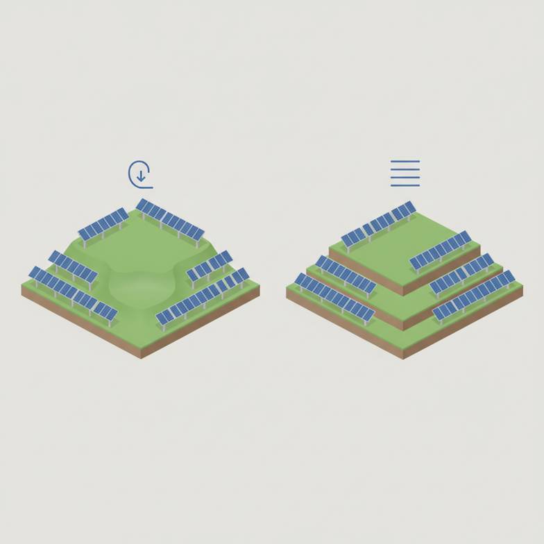
Following the contour means you're installing the solar array directly onto the existing slope with minimal grading. Think of it as draping the array over the land as it is.
From my experience talking with developers, this is often the first choice for sites with gentle to moderate slopes, typically under 15% (around 8.5 degrees).
Pros:
Lower Civil Works Costs: This is the big one. You avoid the massive expense of moving earth, which can save a significant portion of the budget.
Less Environmental Impact: By not disturbing the topsoil and natural drainage patterns, you often face a smoother and faster permitting process.
Faster Project Start: With less site prep, your team can get to work installing foundations and racking much sooner.
Cons:
Requires More Complex Racking: To accommodate the changing slope, you need an adjustable mounting system. This means posts of varying lengths and racking components that can handle grade changes from post to post. These systems can be more expensive than their fixed-tilt counterparts.
Potentially Slower Installation: While you save time on grading, the installation crew may need more time to adjust each post and rail section to match the terrain, which can increase labor costs.
Inter-Row Shading Concerns: On east-west facing slopes, shading from one row of panels onto the next can be a problem, requiring careful layout design and potentially wider spacing.
The Case for Terracing (Cut and Fill)
Terracing involves grading the site to create a series of flat, level "benches" for the solar arrays. It's a full-on civil engineering operation where you cut into the high side of the slope and use that soil to fill the low side.
This approach is often considered for steeper slopes or when a developer wants to use a standardized, non-adjustable mounting system across a large, multi-megawatt project.
Pros:
Uses Simpler, Cheaper Racking: Once the ground is flat, you can use the most cost-effective, fixed-tilt ground mount systems. The parts are uniform, and procurement is simpler.
Faster Racking Installation: On a level surface, installation crews can work much faster, repeating the same simple assembly process over and over again.
Predictable Array Geometry: A flat surface eliminates complex shading calculations and ensures a uniform, clean look.
Cons:
High Upfront Civil Works Costs: Earthmoving is expensive. You're paying for heavy machinery, operators, fuel, and time. This can be a huge line item in your budget.
Major Site Disturbance: Terracing creates significant environmental impact, affecting topsoil, drainage, and local ecosystems. It can also trigger more stringent and lengthy permitting requirements.
Soil Stability Risks: You are fundamentally changing the ground. The "fill" sections must be properly compacted to avoid settling over time, which could compromise the foundations. This often requires a new geotechnical assessment after the grading is done.
Comparison: Terracing vs. Following the Contour
| Feature | Following the Contour | Terracing (Cut and Fill) |
|---|---|---|
| Upfront Cost | Lower (less civil works) | Higher (major earthmoving) |
| Mounting System | More complex, adjustable | Simpler, standardized |
| Hardware Cost | Higher per unit | Lower per unit |
| Installation Speed | Slower racking assembly | Faster racking assembly |
| Environmental Impact | Minimal | Significant |
| Best For | Gentle slopes (<15%), rocky soil | Steeper slopes, soft soil |
What's the Best Foundation for Solar Mounting on Sloped Land?
After you have a layout strategy, the next question I always get is, "So, what's the best foundation?" Everyone is hoping for a simple answer like "ground screws" or "driven piles." The truth is, choosing a foundation without data is just a guess.
The best foundation for your project is the one that is structurally sound for your specific ground conditions, cost-effective to install with local labor and equipment, and can be deployed within your project's timeline. This decision must be driven by a geotechnical report.
Let's break down the common options and where they fit.
Driven Piles (I-Beams, C-Posts)
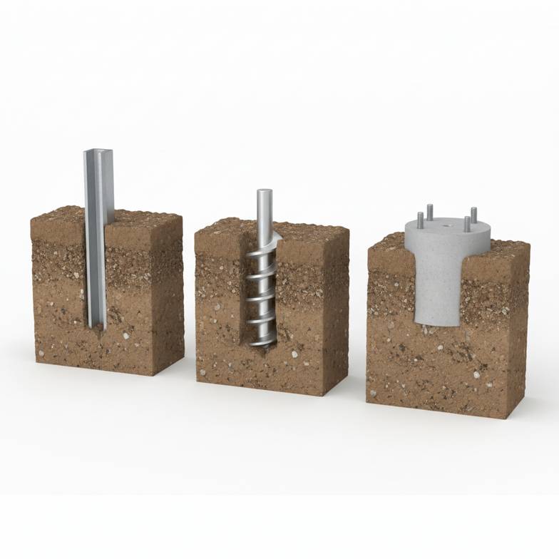
This is the workhorse of utility-scale solar. A driven pile is typically a galvanized steel I-beam or C-channel post that is hammered directly into the ground with a hydraulic ram (a pile driver).
I've seen these used successfully on countless projects with moderate slopes and cooperative soil. They are fast and, in the right conditions, very economical.
How they work: The pile is driven to a specified depth (the embedment depth) until it reaches the required load-bearing capacity. The friction of the soil against the post provides most of the holding power.
Pros: Very cost-effective for large projects, extremely fast installation (a good crew can install hundreds per day), and well-understood by most solar installers.
Cons: They are not suitable for all ground conditions. Shallow bedrock, large boulders ("refusal"), or very loose, sandy soils can prevent piles from being driven to the correct depth or achieving the necessary pull-out strength.
Ground Screws (Helical Piles)
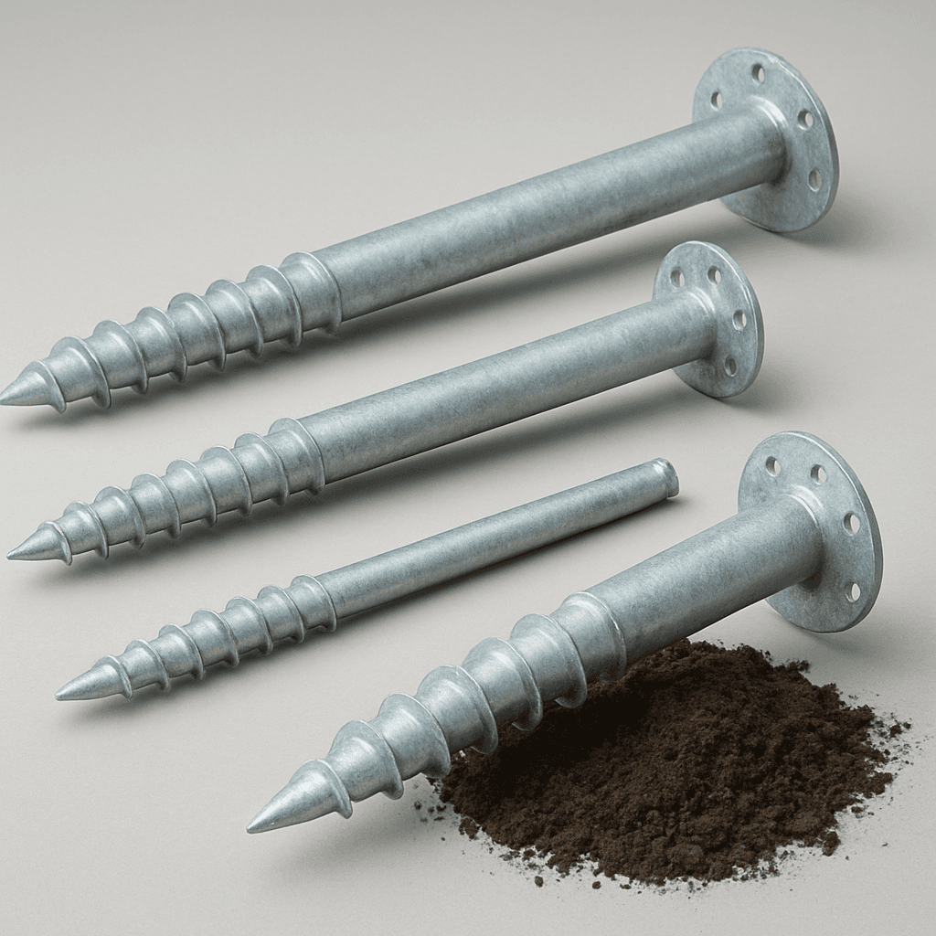
Ground screws are large, galvanized steel screws that are twisted into the ground using a hydraulic drive head, often attached to an excavator or skid steer.
They are an excellent problem-solver, especially in difficult soil conditions where driven piles won't work. They offer more flexibility but generally come at a higher price point per foundation.
How they work: The helical plates (the "threads") on the screw pull it into the ground and then provide pull-out and lateral resistance by displacing a column of soil.
Pros: Excellent performance in a wider range of soils, including some rocky and dense clay conditions. They cause minimal ground disturbance and vibration, and their height can be easily adjusted after installation, which is a huge plus for solar mounting on sloped land.
Cons: Higher material cost per foundation point compared to driven piles. Installation can be slower, and they require specialized torque-monitoring equipment to ensure they are installed correctly.
Concrete Piers (Ballasted or Cast-in-Place)
When all else fails, there's concrete. This can either be a pre-cast concrete block that sits on the ground (a ballasted system) or a hole that is augered and filled with concrete to create a pier (cast-in-place).
This is often the foundation of last resort for the most challenging sites—areas with solid rock, highly corrosive soil, or where pull-out requirements are extreme.
How they work: A large mass of concrete provides stability. For cast-in-place piers, a steel rebar cage is typically inserted before the pour, and a mounting bracket is set into the wet concrete.
Pros: Incredibly versatile and can be engineered for almost any ground condition. They offer immense strength and stability.
Cons: By far the most expensive and time-consuming option. It involves excavation, rebar, concrete trucks, and curing time, all of which add significant cost and complexity to the project schedule.
What Information is Crucial for a Solar Mounting on Sloped Land Proposal?
You want a fast, accurate quote for your project. I get it. But a common frustration I hear from new customers is why we, as suppliers, need so much documentation. Why can't we just give a price for a 1 MW system?
The reason is simple: for solar mounting on sloped land, a proposal without site-specific data is pure guesswork. To design a safe, reliable, and cost-effective system, we need to know exactly what we are dealing with.
Suppliers need a complete data package to engineer a solution rather than just quote a price on a pile of parts. The three most critical documents are the topographical survey, the geotechnical report, and the project's structural load requirements.
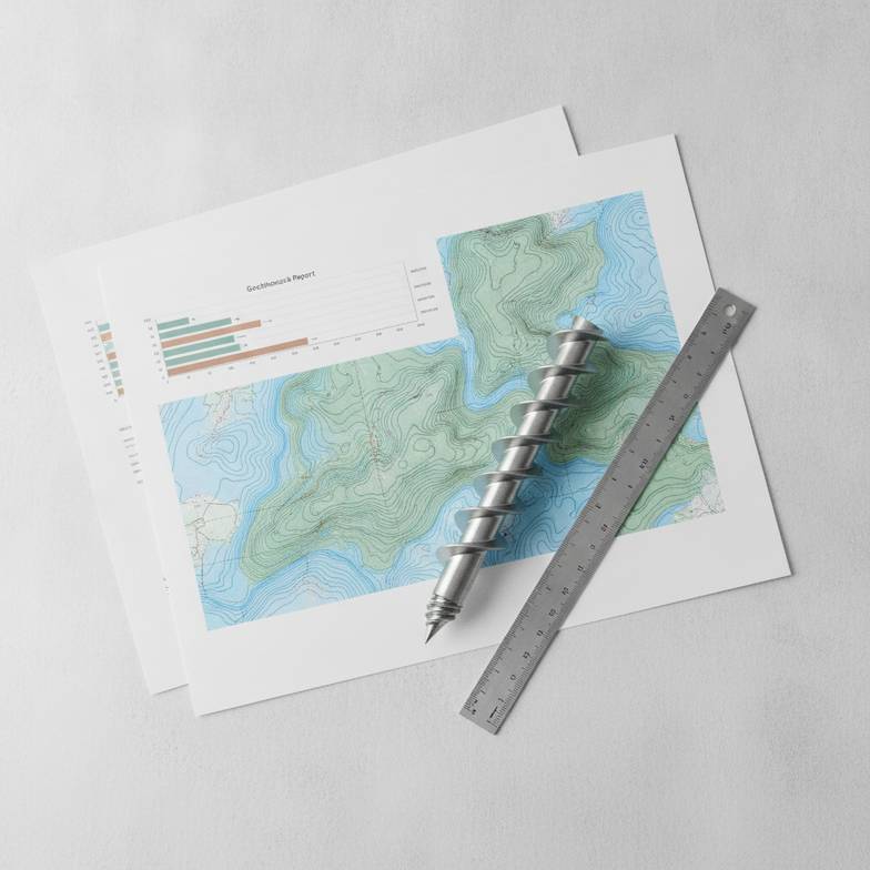
The Topographical Survey (Topo)
This is a detailed map created by a surveyor that shows the precise contours and elevations of your land.
What it tells us: The exact grade of every part of the site. It reveals if a 5% average slope has hidden sections of 15% or 20% that would be impossible to build on without grading.
Why it's essential: The topo map is the foundation for the entire layout. It allows the engineering team to run different layout options (contour vs. terrace), calculate the required post lengths for every location, and perform accurate shading analysis. Without it, everything is a rough estimate. I once had a client who was certain their site was fine, but the topo revealed a gully running right through the middle that would have required a complete redesign.
The Geotechnical Report (Geo-Report)
This report is prepared by a geotechnical engineer who analyzes soil samples from boreholes drilled across your site.
What it tells us: Soil type (clay, sand, loam), density, load-bearing capacity, depth to bedrock, presence of groundwater, and soil corrosivity.
Why it's essential: This is the document that determines your foundation choice.
It tells you if driven piles will work or if you'll hit refusal.
It dictates the required embedment depth and spacing of the foundations.
It determines the level of corrosion protection needed for the steel posts (e.g., G90 vs. G235 galvanization), which has a direct impact on cost and project lifespan.
Structural Load Requirements
This information, typically provided by the project's lead engineer, specifies the forces the mounting structure must be designed to withstand.
What it tells us: The required wind load (e.g., 120 mph, Exposure C) and snow load (e.g., 30 psf) based on local building codes (like ASCE 7) and site conditions.
Why it's essential: Wind and snow loads are the primary forces acting on a solar array. These numbers directly dictate the size, thickness, and spacing of every component in the mounting system—from the posts and rails to the clamps and bolts. A higher wind load means a heavier, more robust (and more expensive) structure.
Frequently Asked Questions
Can you install solar panels on a steep slope?
Yes, but it comes with significant challenges and costs. Slopes greater than 15-20% often require extensive civil works like terracing, specialized installation equipment, and more robust foundation engineering. The project's financial viability must be carefully assessed.
How does slope affect solar panel efficiency?
The primary effect is structural, not electrical. However, the orientation of the slope can impact production. South-facing slopes (in the northern hemisphere) are ideal. East or west-facing slopes can cause inter-row shading in the morning or afternoon, which requires careful layout design to minimize production losses.
Are ground screws always better than concrete for sloped land?
Not necessarily. Ground screws are an excellent solution for many sloped sites due to their adjustability and minimal disturbance. However, in very soft soils or areas with large, solid rock, cast-in-place concrete piers might be the only structurally sound or cost-effective option. The geotechnical report is the ultimate decider.
How much extra does solar mounting on sloped land cost?
There is no simple percentage. The extra cost is a combination of factors: potentially higher civil works costs (if grading), more expensive adjustable racking systems, longer or more numerous foundations, and potentially increased labor for installation on difficult terrain. A thorough analysis using site-specific data is needed to get an accurate number.
Conclusion
Successfully developing a project that involves solar mounting on sloped land isn't about finding a magical product. It’s about following a disciplined process. First, you must analyze your site's topography and decide on a layout strategy—following the contour or investing in terracing. Second, you must obtain a geotechnical report to make an informed, data-driven decision on the right foundation type for your specific ground conditions. Only by combining these critical inputs can a supplier like us engineer a system that is safe, reliable, and commercially viable for the long term.
If you are planning a ground-mount project on challenging terrain, don't get stuck on guesswork. Let's work together. Submit your project's topographical survey, geotechnical report, and structural load requirements, and our team at XINVOK will provide a detailed technical proposal and quotation tailored to your site's unique needs.
Written by
XINVOK Technical Team
Practical solar mounting knowledge for EPC teams, distributors and project buyers.
Project inquiry
Talk to Our Team
Share your project location, module size, mounting type, quantity and customization requirements.